
Description
The nature of transmission networks will change and grow in importance due to Smart Grid. The increased distance of bulk power generation and load centres will result in a tendency to interconnect systems that used to be independent. Furthermore, the exchange and trade of power over long distances will grow in the future.
Information exchange may be necessary across large geographical areas and across traditional systems operation boundaries.
Transmission networks are equipped for obtaining a large number of measurement values; they are able to determine the current load flow situation by means of estimation algorithms. In an estimate, the algorithm uses a numerical network model to try to find a load flow solution in which the difference between the load flow solution and measurement values is minimal. The estimation of the network state supplies the operator with a complete load flow solution for supervising the network, including those sections of the network for which no measurement values are transmitted to the control system.
The network state estimation is generally followed by a limit value monitoring process that compares the result of the estimation with the operating limits of the individual operational equipment, in order to inform the operator about overloads or other limit value infringements in a timely fashion.
The load flow solution of the network state estimation is then used for ongoing functions such as outage analysis, short-circuit analysis or optimizing load flow as a basic solution for further calculations.
The outage analysis carries out “What if?” studies in which the failure of one or more items of operational equipment is simulated. The results of these load flow calculations are then compared with the operational equipment limits in order to be able to detect secondary faults resulting from an operational equipment failure. If such violations of the so-called (n-1) security are detected, an attempt can be made by, for example, using a bottleneck management application to define measures with which (n-1) security can be re-established.
The short-circuit analysis simulates short-circuit situations for all kinds of different network nodes on the basis of numerical model calculations. It checks whether the ensuing short-circuit currents are within the operational equipment limits. The quantities to be checked are the breaking power and the trip time of the circuit breakers and the peak short-circuit current strength of the systems. Here again, the operator is informed about any limit violations so that suitable remedial action can be taken in a timely fashion.
The optimizing load flow attempts to determine an optimum network state by varying the controlled variables in the power supply system. The following target functions for “optimum” are possible:
The voltage/reactive power optimization attempts to minimize the reactive power flow in the network in order to reduce voltage drops and transmission losses. In particular, the reactive power generation of the generators or compensation equipment act as controlled variables.
The active power optimization system tries to minimize the transmission losses by re-dispatching the incoming supplies from the generator.
If system reliability has been selected as the target function of the optimization, the optimizing load flow tries to find a system state in which the capacity of all operational equipment is utilized as evenly as possible. The purpose of this is to avoid further secondary failures in the event of failure of heavily utilized resources.
The challenge posed by Smart Grid implementation and the increased use of bulk power transmission will be a change from the quasi-static state of the transmission grid to a more complex and dynamic behaviour. Therefore, the current available supervision, management and control functions will need to be adapted.
State estimation, for example, will have to include the transient behaviour of the network. In addition, the traditional power, voltage and current measurements need to be extended to phasor measurement provided by PMUs (Phasor Measurement Units).
An optimal representation and visualization as well as decision-supporting tools are expected to be developed in order to support the operator of such complex systems. This will require a large amount of data need to be transmitted, synchronized and represented in a way to safeguard the system integrity of the overall transmission network.
Available standards
The standards listed below are available on IEC webstore.
|
Layer |
Standard |
Title and comments |
|
Information |
IEC 61970 series |
Energy management system application program interface (EMS-API) |
|
Information |
IEC 61970-301 |
Part 301: Common information model (CIM) base |
|
Information |
IEC 61970-302 |
Part 302: Common information model (CIM) dynamics |
|
Information |
IEC 61970-452 |
Part 452: CIM static transmission network model profiles |
|
Information |
IEC 61970-456 |
Part 456: Solved power system state profiles |
|
Communication |
IEC 61970-501 |
Part 501: Common Information Model Resource Description Framework (CIM RDF) schema |
|
Communication |
IEC 61970-552 |
Part 552: CIMXML Model exchange format |
|
Communication |
IEC 60870-5-101 IEC 60870-5-104 IEC 60870-6 |
Telecontrol equipment and systems |
|
Information, communication |
IEC 61850 series |
Communication networks and systems for power utility automation See substation automation Erreur ! Source du renvoi introuvable.systems |
|
Communication |
IEC TR 61850-90-2 |
Part 90-2: Using IEC 61850 for communication between substations and control centres |
|
Communication |
IEC TR 61850-90-5 |
Part 90-5 Use of IEC 61850 to transmit synchrophasor information according to IEEE C37.118 |
|
Information |
IEC 62361-2 |
Power systems management and associated information exchange – Interoperability in the long term – Part 2: End to end quality codes for supervisory control and data acquisition (SCADA) |
|
Communication |
IEC 62361-100 |
Power systems management and associated information exchange – Interoperability in the long term – Part 100 CIM profiles to XML schema mapping |
|
Information |
IEC TS 62361-102 |
Power systems management and associated information exchange – Interoperability in the long term – Part 102: CIM - IEC 61850 harmonization |
|
General |
IEC TR 62357-1 |
Power systems management and associated information exchange – Part 1: Reference architecture Reference architecture power system information exchange |
|
Communication |
IEC TR 62357-200 |
Guidelines for migration from Internet Protocol version 4 (IPv4) to Internet Protocol version 6 (IPv6) |
|
Communication |
IEC 62351 series |
Power systems management and associated information exchange – Data and communications security Cyber-security aspects |
|
Information Communication |
IEC 62325 series |
Framework for energy market communications |
|
Other specifications |
||
|
Communication |
IEEE 1815 |
IEEE Standard for Electric Power Systems Communications-Distributed Network Protocol (DNP3) |
|
Information |
IEEE 1815-1 |
IEEE Standard for Exchanging Information Between Networks Implementing IEC 61850 and IEEE Std 1815 |
Coming standards
|
Layer |
Standard |
Title and comments |
|
Communication |
IEC 60870-5-7 |
Telecontrol equipment and systems - Part 5-7: Transmission protocols - Security extensions to IEC 60870-5-101 and IEC 60870-5-104 protocols (applying IEC 62351) |
|
Information |
IEC 61970-302 Ed 2 |
Energy management system Application Program Interface (EMS-API) – Part 302: Common information model (CIM) dynamics |
|
Information |
IEC 61970-457 Ed 2 |
Energy management system Application Program Interface (EMS-API) – Part 457: Dynamics profile |
|
Information |
IEC 61850-7-410 Ed 3 |
Communication networks and systems for power utility automation -- Part 7-410: Basic communication structure - Hydroelectric power plants - Communication for monitoring and control |
|
Communication |
IEC 61850-80-6 |
Communication networks and systems for power utility automation – Part 80-6: Using IEC 61850 for communication between substations and control centres This will replace IEC 61850-90-2 |
|
Communication |
IEC 61850-80-7 |
Communication networks and systems for power utility automation - Part 80-7: Communication services and data model to support IEC 61850 system management This will facilitate more rapid and coordinate deployment of upgrades for remote sites. |
|
Information |
IEC 62746-4 |
Systems interface between customer energy management system and the power management system - Part 4: Demand Side Resource Interface |
|
Communication |
IEC 62361-104 |
Power systems management and associated information exchange -- Interoperability in the long term - Part 104: CIM Profiles to JSON Schema Mapping |
|
Information |
IEEE 1815.2 |
DNP3 profile for DER communications |
Mapping of standards
on the component layer

The EMS SCADA component architecture is given in the Figure above. Data and information of the actual status of the transmission system is online available through the RTUs of all substations in the network. The transmission network is operated and controlled from the dispatch centres by remote controlled circuit breakers in all relevant fields of the network. The operators are supported (coached and controlled) by the EMS SCADA system regarding energy flows in the network, during normal, maintenance and emergency operation of the network or parts of it.
Mapping of standards
on the communication layer

Communication protocols from the substation automation domain can be used because the EMS SCADA system interacts with the protection, monitoring and control systems in the substations. Furthermore, the EMS SCADA will have direct interaction with power plants connected to the transmission system and Transmission System Operators (TSO) are responsible for balancing power generation and demand. Finally, TSOs have a responsibility in supporting the energy market interactions to bulk generation connected to the substations in their EHV and HV transmission networks.
The set of standards representing the related protocols regarding EMS SCADA can be positioned as shown in the Figure above. This diagram shows the communication layer of Smart Grid Architecture Model. The significant standards regarding communication are IEC 60870-5-101 and IEC 60870-5-104 to connect power plants to the grid.
Mapping of standards
on the information layer
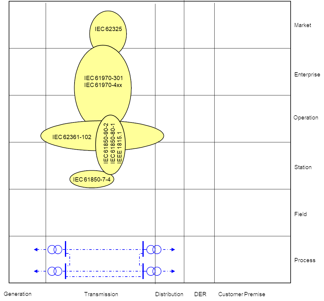
The information layer of EMS SCADA, as shown in the Figure above, is based on standards and guidelines that cover the Information Models relevant for EMS SCADA Systems used for operating the EHV and HV networks of TSOs.