
Description
The power grid faces a number of challenges: in view of the steadily growing connection of renewable energy and of the demand for electricity, network capacities need to be expanded, availability improved, and congestion and outages avoided. All this needs to be performed in the most cost-efficient way possible, in consuming as little as possible of CAPEX (Capital expenditure) then taking maximum benefits of already installed assets, and in consuming as little as possible of OPEX (Operational expenditure). This means extending average life cycles and minimizing maintenance costs.
The Smart Grid vision therefore includes solutions like Condition Monitoring in order to make full use of existing infrastructure. Condition Monitoring provides all the technical information required to maintain availability and at the same time maximize performance, including loading and lifetime benefits. The Condition Monitoring solution surveys every link in the energy supply chain. Accurate monitoring of all primary components of a substation makes optimized loading and performance possible and helps to increase the useful life of the substation.
Additionally, Condition Monitoring systems contribute to network optimization down to each element in terms of efficiency and reliability. It provides valuable information and reliable diagnostics. Failures can be predicted, unscheduled downtime is thus reduced, and equipment useful life is extended to a significant degree. This feature is called condition-based maintenance. In addition, capacity data analysis can provide recommendations on how to maximize asset performance and can lever existing overloading capabilities, especially of transformers and overhead lines. This optimizes grid operation and grid asset management.
The choice of the assets to be monitored in each asset type shall be justified by a risk-informed decision and a cost-benefit analysis. Condition monitoring is an option to consider among other options, for the management of assets
along their lifecycle. Management of assets and Condition Monitoring System can include the following elements:
· Transformer Monitoring: The main components
monitored are cooling, bushings, tap changer and oil quality.
· GIS Monitoring: The main parameters for GIS monitoring are SF6 pressure, density and partial
discharge.
· Circuit Breaker Monitoring: In order to monitor the performance of the circuit breaker, key parameters, such as the contact separation speed and
the operation time of the circuit breaker, need to be recorded. This can be achieved by a range of transducers providing signal input. The signals need to be digitized at a frequency that provides sufficient sample points to allow
accurate and early assessment of a developing problem.
· Isolator- and Earthing-Switch Monitoring.
· Overhead
Line Monitoring: The main parameters are OHL clearance and ampacity.
· Cable Monitoring: Assessment of an installed cable can be achieved, for example, through
the line impedance phase shift and the HotSpot Detector signature. The first indicator is used both for local and global aging assessment. For local fault detection, the two indicators work together, where the phase shift is used
as a real-time early warning of a developing fault and the Hot-spot detector quantifies and localizes the fault along the cable.
· Surge Arrester Monitoring.
· Current Transformer and Voltage Transformer Monitoring.
· Balance of Plant Monitoring: Monitoring of supplementary
BoP equipment, especially batteries and diesel engines.
· Secondary Equipment Monitoring.
· Predictive
diagnoses and prognoses.
Unlike “islanded”, individual condition monitoring systems for each asset, which have already been available on the market for some time, advanced Condition Monitoring makes a combination of individual modules possible on a common communication platform.
Available standards
The standards listed below are available on IEC webstore.
|
Layer |
Standard |
Title and comments |
|
Information |
IEC 61360 |
Common Data Dictionary available from <http://std.iec.ch/iec61360> |
|
Information |
IEC TR 61850-90-3 |
Communication networks and systems for power utility automation – Part 90-3: Using IEC 61850 for condition monitoring diagnosis and analysis |
|
Information |
IEC TS 61850-80-1 |
Communication networks and systems for power utility automation – Part 80-1: Guideline to exchanging information from a CDC-based data model using IEC 60870-5-101 or IEC 60870-5-104 |
|
Communication, information |
IEC TR 61850-90-2 |
Communication networks and systems for power utility automation – Part 90-2: Using IEC 61850 for the communication between substations and control centres |
|
Information, communication |
IEC 61400-25 series |
Wind turbines – Communications for monitoring and control of wind power plants |
|
Information |
IEC 61968-4 |
Application integration at electric utilities – System interfaces for distribution management – Part 4: Interfaces for records and asset management |
|
Information |
IEC 61968 series |
Application integration at electric utilities – System interfaces for distribution management CIM Distribution |
|
Information |
IEC 61968-6 |
Application integration at electric utilities – System interfaces for distribution management – Part 6: Interfaces for maintenance and construction |
|
Information |
IEC 61970 series |
Energy management system application program interface (EMS-API) CIM Transmission |
|
Communication |
IEC 61850-8-1 |
Communication networks and systems for power utility automation – Part 8-1: Specific communication service mapping (SCSM) – Mappings to MMS (ISO 9506-1 and ISO 9506-2) and to ISO/IEC 8802-3 IEC 61850 communication except Sample values |
|
Communication |
IEC 60870-5-101 |
Telecontrol equipment and systems – Part 5-101: Transmission protocols – Companion standard for basic telecontrol tasks |
|
Communication |
IEC 60870-5-104 |
Telecontrol equipment and systems – Part 5-104: Transmission protocols – Network access for IEC 60870-5-101 using standard transport profiles |
|
Communication |
IEC 61968-100 |
Application integration at electric utilities – System interfaces for distribution management – Part 100: Implementation profiles Defines profiles for the communication of CIM messages using Web Services or Java Messaging System. |
|
Asset type |
IEC 60076 series |
Power transformers |
|
Asset type |
IEC 62271-1 series |
High-voltage switchgear and controlgear |
|
Asset type |
IEC 62271-2 series |
High-voltage switchgear and controlgear assemblies |
|
Asset type |
IEC 61897 |
Overhead lines – Requirements and tests for Stockbridge type aeolian vibration dampers |
Coming standards
|
Layer |
Standard |
Title and comments |
|
Information, communication |
IEC 61400-25 series |
Wind turbines – Communications for monitoring and control of wind power plants Edition 2 – Set of standards more specific to wind turbines and wind farms |
|
Communication |
IEC 61850-8-2 * |
Communication networks and systems for power utility automation – Part 8-2: Specific communication service mapping (SCSM) – Mapping to Extensible Messaging Presence Protocol (XMPP) IEC 61850 communication mapping on Web-services |
|
* Under preparation. |
||
Mapping of standards
on the component layer

The Asset Management component architecture ranges from the Process zone to the Enterprise zone as shown in the Figure above:
· At the Enterprise zone the Asset
Management system itself is located.
· At the Operation zone the Condition Monitoring systems are located.
· The Station
and Field zone provide the communication with the sensors that monitor the assets and with the field force.
· The assets are located at the Process zone.
Note: AS means “Application Server”.
Mapping of standards
on the communication layer

The communication between the field, station and operations is done via IEC 61850 or through IEC 60870-5-101 or IEC 60870-5-104. For the enterprise bus communication between the operation and enterprise zone components the coming standard IEC 61968-100 is used. Note that IEC 61968-100 is defined for the IEC 61968 series information models, but the same web services approach can be applied to the IEC 61970 information models. For field force communication the substation to operations communication infrastructure and dedicated networks (e.g. mobile networks) can be used.
Mapping of standards
on the information layer
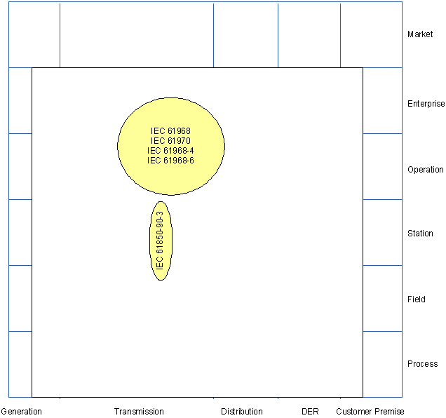
For the condition monitoring information exchange between the field/station and operations zone the coming standard IEC TR 61850-90-3 will be used. IEC 61968 and IEC 61970 standards in general apply for providing asset management related information. Specifically, IEC 61698-4 and the coming standard IEC 61968-6 define CIM interfaces for asset and maintenance management for the distribution domain. For the other domains no specific asset and maintenance management standards exist.